Total Annihilation has a special place in my heart since it was the very first RTS I played;
it was with Command & Conquer and Starcraft one of the best RTS released in the late 90’s.
10 years later – in 2007 – its successor was released: Supreme Commander.
With Chris Taylor as the designer, Jonathan Mavor
in charge of the engine programming and Jeremy Soule as the music composer (some of the main figures behind the original Total Annihilation), the expectations of the fans were very high.
Supreme Commander turned out to be highly praised by critics and players, with nice features like the “strategic zoom” or physically realistic ballistic.
So let’s see how Moho, the engine powering SupCom, renders a frame of the game!
Since RenderDoc doesn’t support DirectX 9 games, reverse-engineering was done with the good old PIX.
Terrain Structure
Before we dig into the frame rendering, it’s important to first talk about how terrains are built in SupCom and which technique is used.
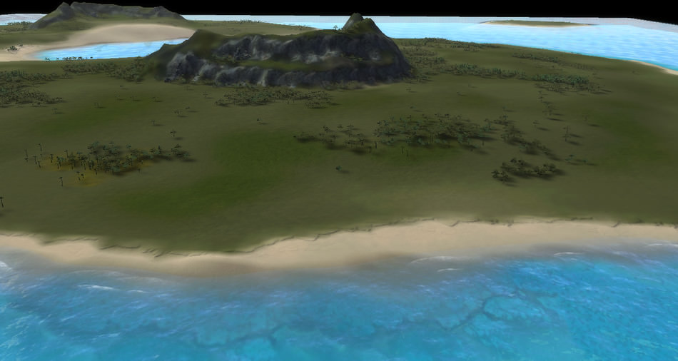
Here is an overview of “Finn’s Revenge”, a 1 versus 1 map.
On the left is a top-view of the entire map like it appears in-game on the mini-map.
Below is the same map viewed from another angle:
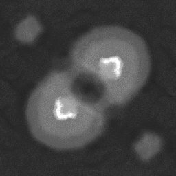
First the geometry of the terrain is calculated from an heightmap.
The heightmap describes the elevation of the terrain. A white color represents a high altitude and a dark one a low altitude.
For our map, a 513x513 single-channel image is used, it represents a terrain
of 10x10 km in-game. SupCom supports much larger maps, up to 81x81 km.
Heightmap
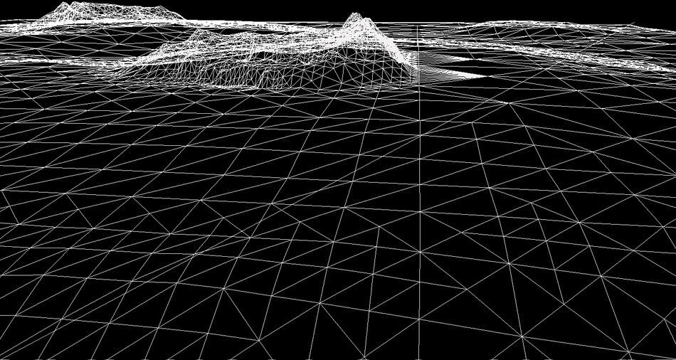
Tessellated Terrain
So we have a mesh which represents our terrain.
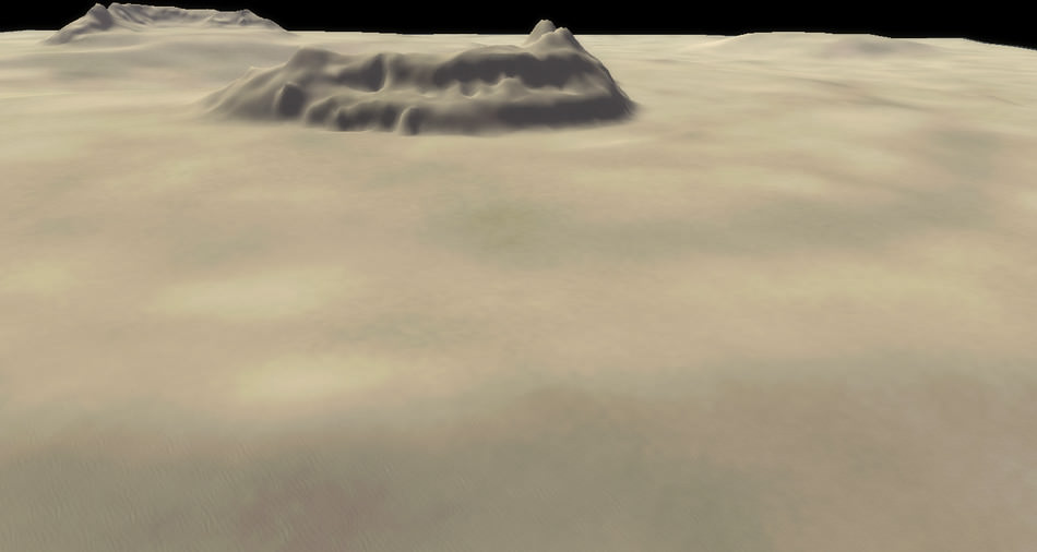
Then the game applies an albedo texture combined with a normal texture to cover all these polygons.
For each map the sea level is also specified so the game modulates the albedo color of the pixels under the sea surface to give them a blue tint.
Wireframe Terrain
Albedo + Normal Textures
Sea Level Color Modulation
Okay so having altitude-based texturing is nice, but it gets limiting quite quickly.
How do we add more details and variations to our map?
When it comes to self-learning Japanese, you can read books,
watch Japanese TV with the JP subtitles on…
However if your level is just beginner or intermediate, you’ll often hit some kanji
you can’t read, some words you don’t know.
Chances are you’ll spend 5 minutes looking up kanji by radicals in the dictionary
to decipher a single page of a manga – the same page you would read under 5 seconds in its English version.
There goes your motivation…
Isn’t there a way to make the whole process more fun and efficient?
I find reading visual novels to be an
interesting approach to making progress in Japanese: the game pauses after each sentence
so, unlike a movie, you can take your time to understand all the words. Plus many novels are fully voiced,
which is really important to learn the intonation.
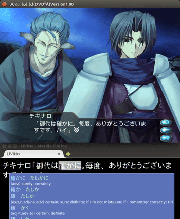
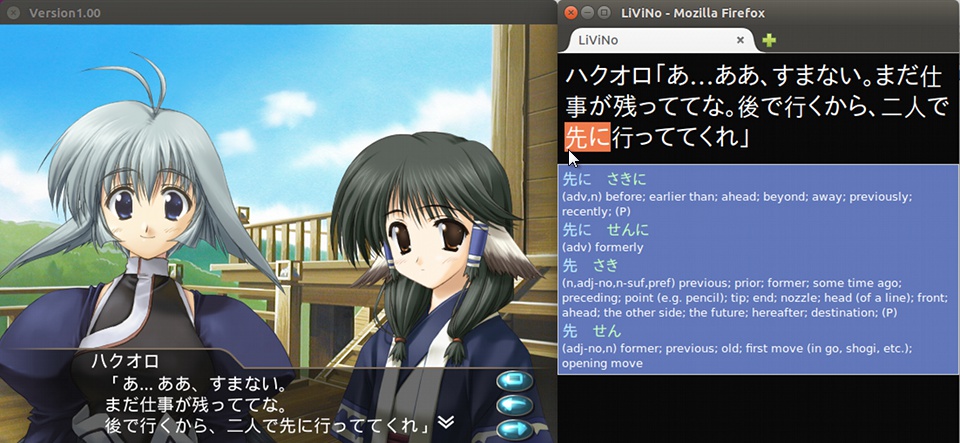
All these games draw Japanese words on your screen, but unfortunately you can’t even select or copy them!
The words are here though, deeply burried in the game binary, if only we could grab them…
So here comes LiViNo Reader: it’s a small hack I wrote to live-stream the text rendered by the game directly to
the Rikaichan dictionary so you can get an instant translation by just hovering a word.
2015/03/12:Back online after Reddit
and Slashdot killed my bandwidth with 30,000 visits in the last hours. Followed by HN. 2015/03/11:Update with comments from Matthijs De Smedt.
The original Deus Ex is among the most critically acclaimed PC games of its time and I spent countless hours helping JC Denton fend off the conspiracies of UNATCO or the Illuminati.
I never had the chance to play the second opus “Invisible War”, but I gave a shot to “Human Revolution” when it was released.
All I can say is: it lived up to the expectations!
Deus Ex: Human Revolution is a game released in 2011 by Square Enix, and developed by Eidos Montréal and Nixxes for the PC version.
It uses a modified version of the Crystal engine made by Crystal Dynamics and was one of the earliest games to support DirectX 11.
It featured great graphics at the time (still looks good!), and it was as beautiful as light-weight: even low-budget video cards could run the game smoothly.
I was curious about the rendering process, so I spent a few hours reverse-engineering the game, playing with Renderdoc.
Here are the results of my investigation.
How a Frame is Rendered
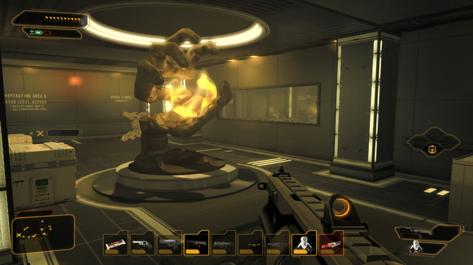
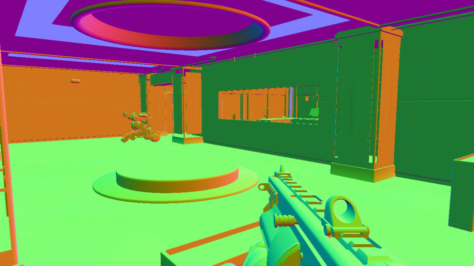
Below is the scene we’ll consider. This is an actual screenshot of the game: the final image presented on the player’s monitor.
Let’s dissect this frame!
At first glance, Deus Ex HR seems to use an approach similar to the forward+ rendering technique.
Except that the game was developed years before forward+ became popular, actually it uses a precursor technique: the “light pre-pass” approach.
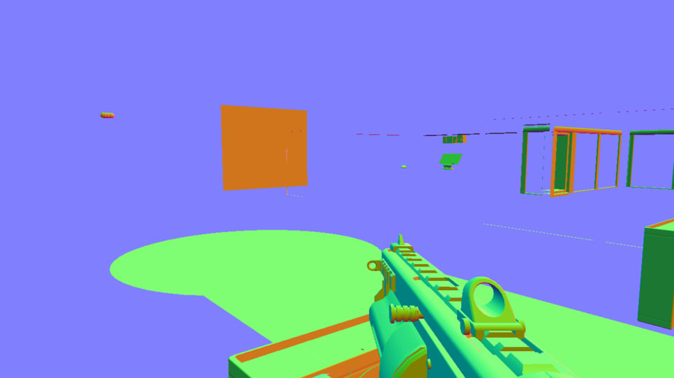
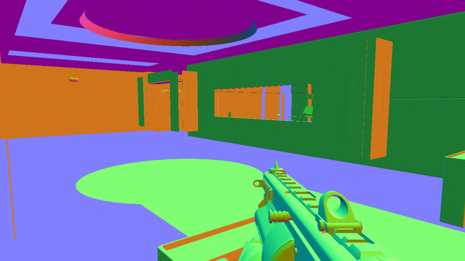
Normal + Depth Pre-Pass
The game renders all the visible objects, outputting only a normal map and a depth map.
Transparent objects are not rendered.
Depending on the mesh, each triangle will be rendered as a flat surface (same normal for all the fragments of the triangle),
or can also be modulated by its own normal map.
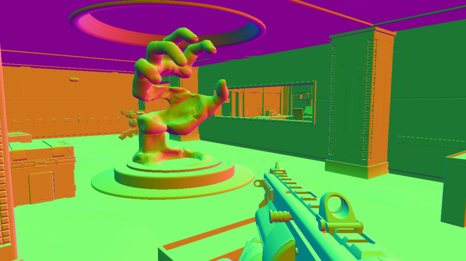
For example, the hand sculpture has its own normal map modulating the final normals rendered to the buffer.
2022/12/15Update: with IRKit cloud officially shutting down this firmware can avoid your device turning into a brick. More discussion on this GitHub thread.
There were still 2 points bugging me with the official firmware:
The LED is always on. It acts like a feedback, to show the user the device is working well. It’s all great and fine unless, like me, you can’t stand yet-one-more-LED lighting-up the dark room at night. I sleep much better in total darkness.
IRKit needs Internet access. During the setup phase, IRKit needs Internet access to validate the device key (used by the cloud control). Also the firmware polls the cloud servers every 25 seconds to check if there are some IR commands to send. I don’t need the cloud feature, I use IRKit Web Remote instead. I wanted a LAN-only mode
for IRKit, it is much more secure than granting the device WAN access.
Navigate to device/firmware/src/IRKit and rename the file version.template to version.c.
Open the file config.h, this is where you can configure the settings:
config.h
12345678910111213141516
// Different modes for the LED feedback.typedefenum{LED_VERBOSE=0,// LED almost always-on to indicate the device status.LED_QUIET=1,// LED on during setup and blinks when receiving/sending commands. Off when the device is idle.LED_SETUP_ONLY=2,// LED on only during the setup, then always-off.LED_OFF=3// /!\ This disables the LED completely.}LedFeedbackProfile;// Defines what kind of LED profile you want.constLedFeedbackProfileledFeedback=LED_QUIET;// Enables/disables cloud-control through the "deviceapi.getirkit.com" server.// If you use your IRKit device exclusively over your LAN, you can disable// this option: the device won't send regular polling requests to the cloud server.// This also lets you setup your device without internet access (no need for a valid device key).constbooluseCloudControl=true;
To modify the LED behavior simply modify the line const LedFeedbackProfile ledFeedback = LED_QUIET; and replace LED_QUIET by either LED_VERBOSE, LED_SETUP_ONLY or LED_OFF.
If you want to enable the offline mode, then set useCloudControl to false. Update:IRKit cloud service being shut down, you absolutely must set this to false otherwise IRKit will fail initializing.
Set up the Arduino environment
You should install the “Arduino IDE” for your OS, the 1.0.6 version is highly recommended and can be found here.
If you absolutely need to use a newer IDE version, the firmware described on this page might not compile out-of-the-box.
It is fortunately relatively easy to update the codebase to compile with 2.x IDEs like described on this GitHub thread.
I’m going to give some more details concerning the setup with Windows because I encountered a few problems.
First install Arduino IDE 1.0.6, it should install the drivers for the Arduino boards also.
Then connect your IRKit to a USB port of your computer.
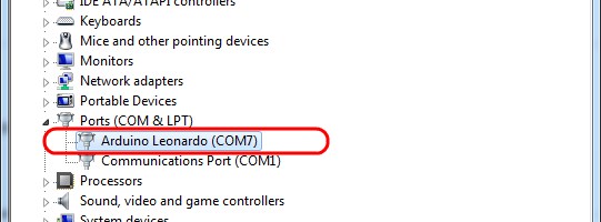
Let’s check if the board is recognized correctly. Open the device manager (‘Computer’, right-click, ‘Properties’, ‘Device Manager’), if the board was recognized it should appear on a COM port, in my case COM7:
If you see your device then congratulations, you can skip the following and go directly to the next step.
But chances are, your device was not recognized and just appears as a yellow question mark in the list.
No worry, we will just be more explicit and tell Windows which driver we want to use.
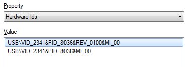
Still inside the Device Manager, right-click on your unrecognized device, ‘Properties’, ‘Details’ tab and in the drop-down menu select ‘Hardware Ids’.
It should display something like this:
Note down the values, we’re going to need them later.
Then navigate to C:\Program Files (x86)\Arduino\drivers and extract the archive Old_Arduino_Drivers.zip.
Edit the file Arduino Leonardo.inf and modify the Vendor and Product ID Definitions section to add the IDs you got previously from the Device Manager:
Save the file, go back to the Device Manager, then right-click, ‘Properties’, ‘Driver’ tab.
Click on ‘Update Driver…’ and ‘Browse my computer for driver software’. For the folder simply provide C:\Program Files (x86)\Arduino\drivers\old_drivers and let Windows install the device.
Windows should now associate the Leonardo driver with your board. Your device should appear as a COM device.
Since we’re still in the ‘Device Manager’ let’s fix one more issue you might run into.
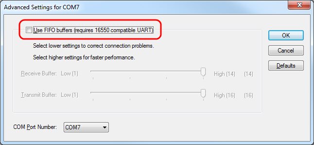
When trying to upload the new firmware to IRKit I got the following error:
avrdude: error: buffered memory access not supported. Maybe it isn't a butterfly/AVR109 but a AVR910 device?
To prevent this problem, right-click on your device, ‘Properties’, ‘Port Settings’ tab, ‘Advanced…’:
Make sure the Use FIFO buffers checkbox is not selected.
Compile and upload the firmware
Go back to the folder with the source code of the firmware (where you edited config.h).
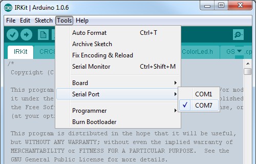
Double-click on IRKit.ino, this will launch Arduino and load the project.
Make sure the correct COM port is selected:
Then simply click on ‘File’, ‘Upload’: this will compile the firmware and upload the binary to the board.
And that’s it! No more bright LED. :)
Note that in some case, flashing the firmware can cause a reset of the EEPROM, meaning the board might forget the credentials to join your home WiFi network so you might have to go through the setup phase again.
An important point: after flashing this custom firmware, the device in setup-mode will always broadcast a WiFi network which password is now XXXXXXXXXX, so don’t try to use the old password you found on the small piece of paper inside the IRKit box.
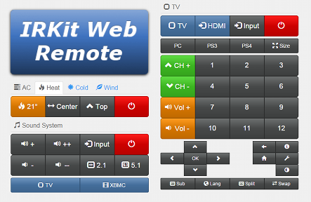
The setup guide was handy as a proof of concept, but I was still lacking a way to organize efficiently all the IR commands I recorded from various remote controls.
So here comes IRKit Web Remote: a web-solution to control and dispatch commands from a web-browser.
I host it on a small Raspberry Pi so anybody in the family can just fire-up a browser on the phone, open the page and send commands.
Having everything centralized on the server is really useful when I need to add new commands: I simply update the web page on
the server and I don’t have to care about maintaining clients one by one, clients will get the latest features upon the next page reload.
A few features of IRKit Web Remote:
supports sending one single command or a series of command (with custom delays between each)
command buffer to avoid overloading IRKit, with current queue visual feedback. Queue is also cancellable.
any size of screen supported thanks to the responsive design of Bootstrap
can be exposed to the Internet (a script forward the POST request within the LAN)
includes the interactive guide to do the initial setup of a new IRKit device
easy to tune and adapt to your needs
The code is on GitHub, feel free to grab it and play with it.