![]()
The Metal Gear series achieved world-wide recognition when Metal Gear Solid became a best-seller on the original PlayStation almost two decades ago. The title introduced many players to the genre of “tactical espionage action”, an expression coined by Hideo Kojima the creator of the franchise.
Though in my case the first time I played as Snake wasn’t with this game but with the Ghost Babel spin-off on GBC, a lesser-known but nevertheless excellent title with an impressive depth.
The final chapter Metal Gear Solid V: The Phantom Pain was released in 2015 and brings the series to a whole new level of graphics quality thanks to the Fox Engine developed by Kojima Productions. The analysis below is based on the PC version of the game with all the quality knobs set to maximum. Some of the information I present here has already been made public in the GDC 2013 session “Photorealism Through the Eyes of a FOX”.
Dissecting a Frame
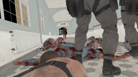
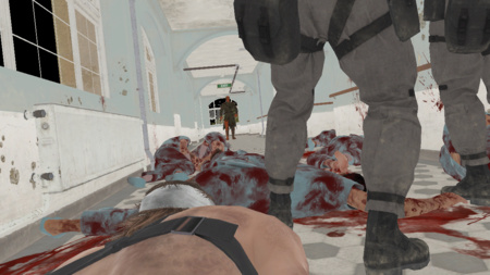
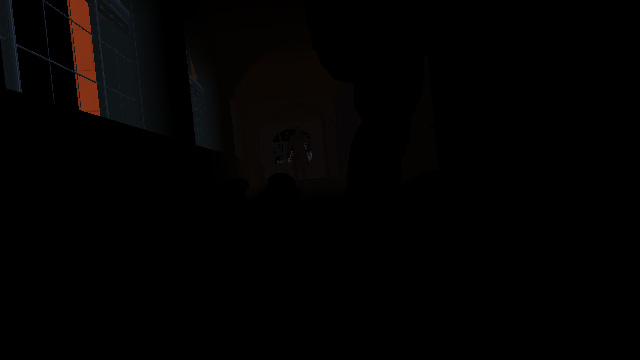
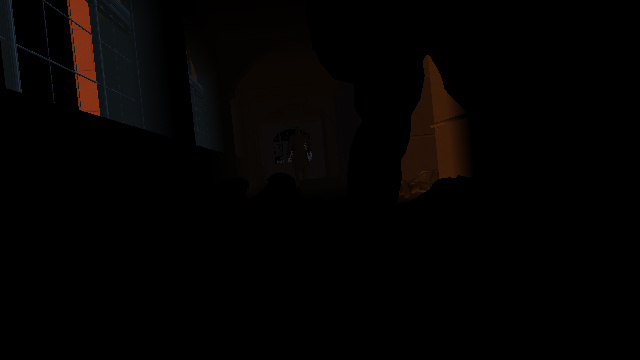
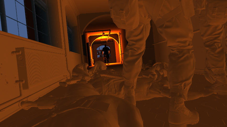
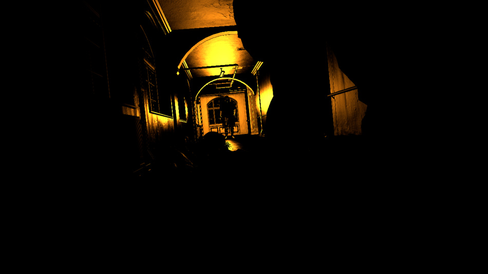
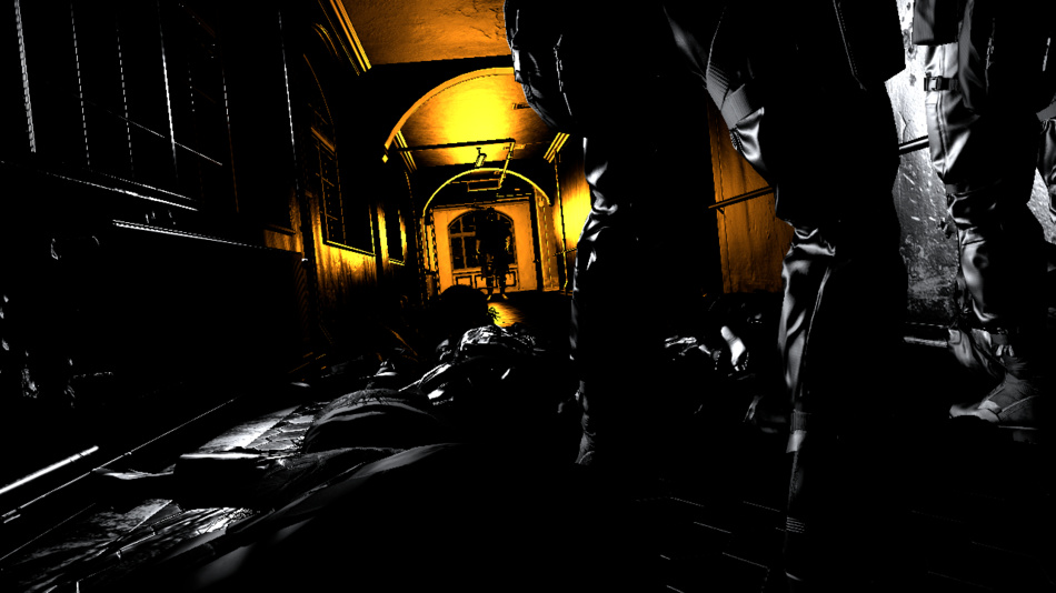
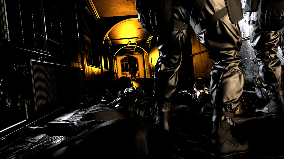
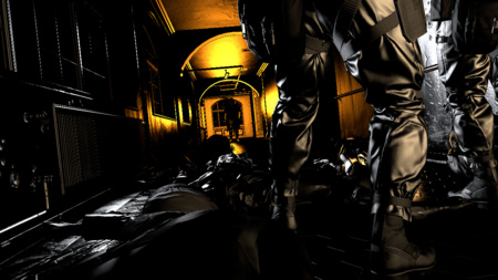
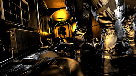
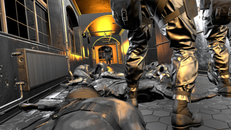
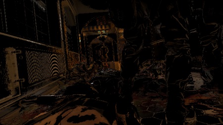
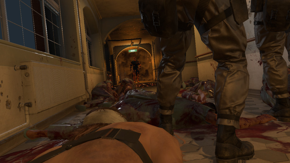
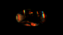
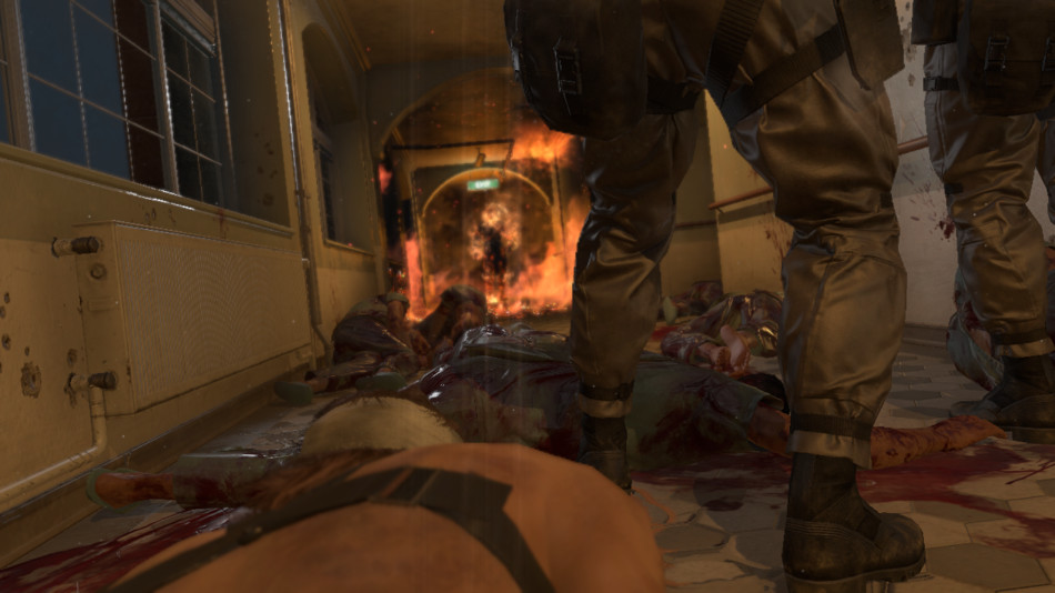
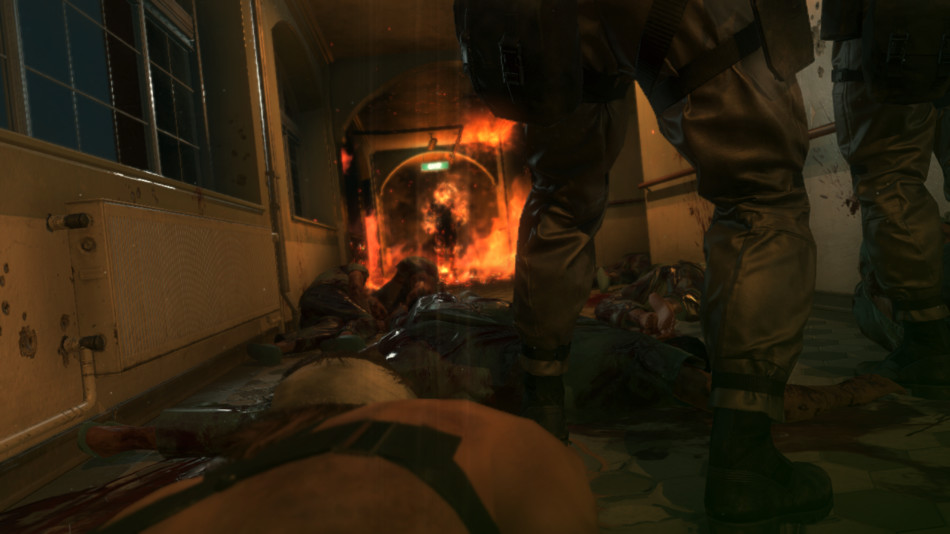
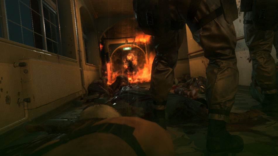
Here is a frame taken from the very beginning of the game, during the prologue when Snake tries to make his way out of the hospital. Snake is lying on the floor trying to blend in among the other corpses, he’s at the bottom of the screen with his naked shoulder. Not the most glamorous scene but it illustrates well the different effects the engine can achieve.
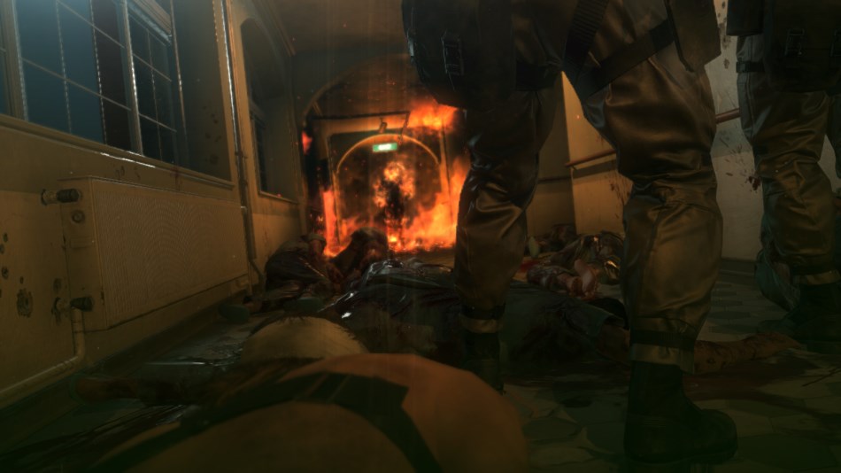
Right in front of Snake two soldiers are standing up, they’re looking at some burning silhouette at the end of the hallway. I’ll simply refer to that mysterious individual as the “Man on Fire” not to spoil anything about the story.
So let’s see how this frame is rendered!
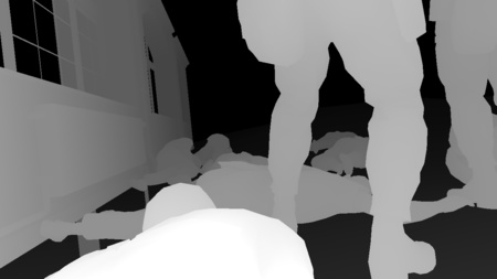
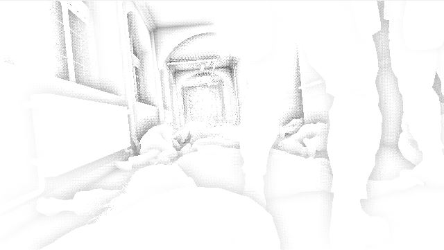
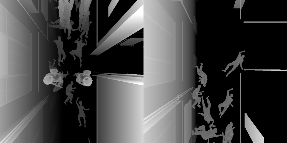
Depth Pre-Pass
This pass renders only the geometry of the terrain underneath the hospital as viewed from the point of view of the player and outputs its depth information to a depth buffer. The terrain mesh is generated from the heightmap you can see below: it’s a 16-bit floating point texture containing the terrain elevation value (view from the top). The engine divides the heightmap into different tiles, for each tile a draw call is dispatched with a flat grid of 16x16 vertices. The vertex shader reads the heightmap and modifies on-the-fly the vertex position to match the elevation value. The terrain is rasterized in about 150 draw calls.

Terrain Elevation
|
|

Depth Map: 5%

Depth Map: 10%

Depth Map: 40%

Depth Map: 100%
|
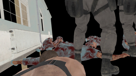
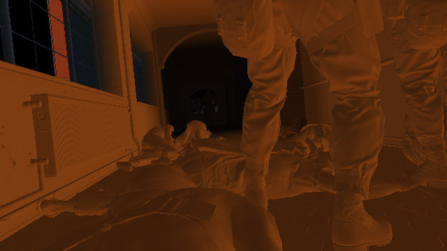
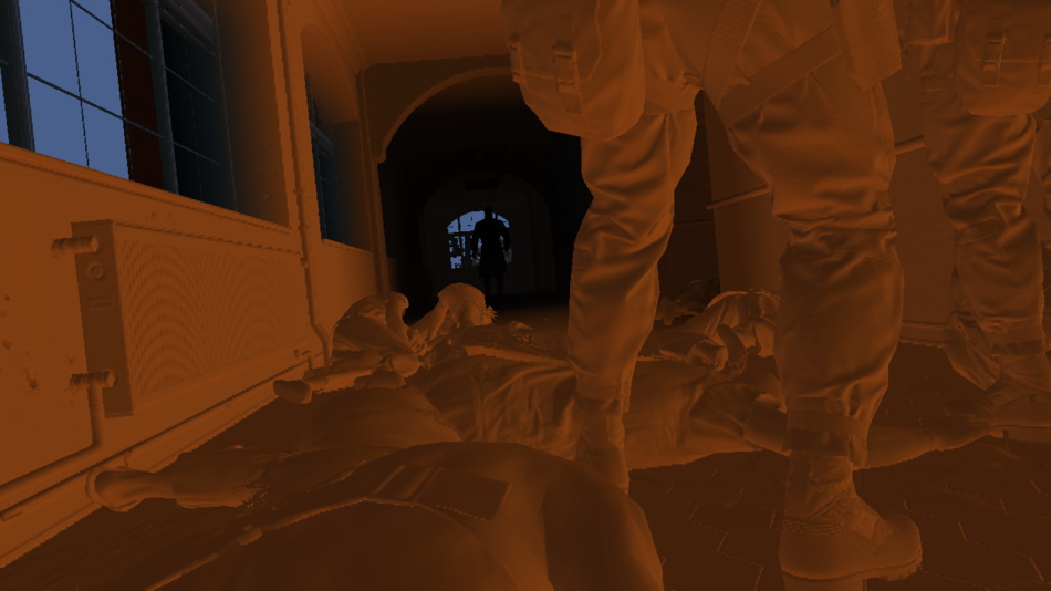
G-Buffer Generation
MGS V uses a deferred renderer like many games of its generation, if you already read the GTA V study you will notice several similar elements. So instead of calculating directly the final lighting value of each pixel as the scene is rendered, the engine first stores the properties of each pixels (like albedo colors, normals…) in several render targets called G-Buffer and will later combine all this information together.
All the following buffers are generated at the same time:
Albedo
|
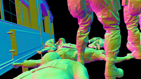
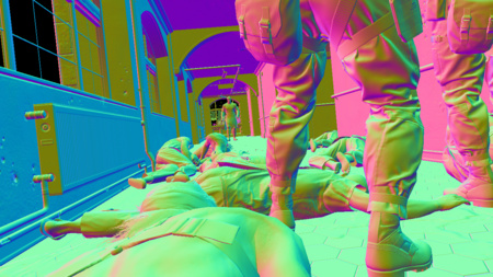
Normal
|
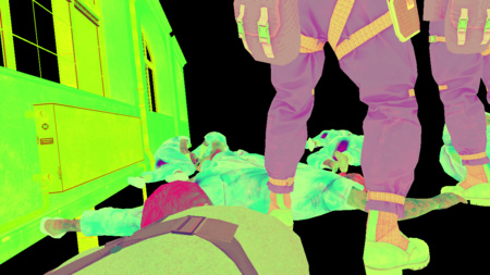
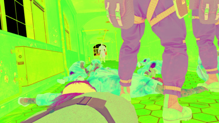
Specular
|
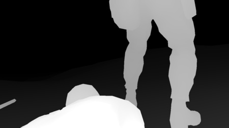
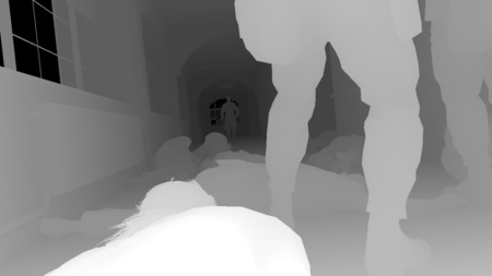
Depth
|
Albedo
|
Normal
|
Specular
|
Depth
|
Albedo
|

Normal
|
Specular
|
Depth
|
Albedo
|
Normal
|
Specular
|
Depth
|
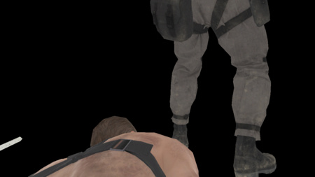
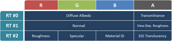
Here we have a relatively light G-Buffer with 3 render targets in B8G8R8A8 format:
- Albedo map: the RGB channels contain the diffuse albedo color of the meshes, the intrinsic color when no lighting is applied. The alpha channel contains the opacity / light “transmittance” value of the material (typically 1 for completely opaque objects, and 0 for grass or foliage).
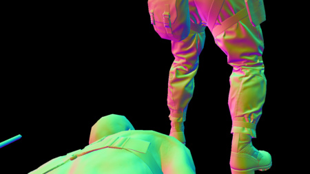
- Normal map: the normal vector (x, y, z) of the pixel is stored in the RGB channels. The alpha channel contains the coefficient for the view-dependent roughness of certain materials.
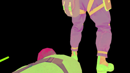
- Specular map:
- Red: roughness
- Green: specular
- Blue: material ID
- Alpha: translucency for the sub-surface scattering (only skin and hair materials seem concerned here)
- Depth map: a 32-bit float representing the depth of the pixel. The depth is also reversed (value of 1 for meshes close to the camera) in order to keep a high floating-point precision for meshes far away and avoid Z-fight. It’s important for open-world games where the draw distance can be very high.
The G-Buffer rendering was done in the following order: first all the opaque meshes of the main scene (characters, hospital building…), then all the terrain (again) and finally the decals.
The depth pre-pass benefit is not especially relevant for this shot since most of the scene is located in front of the terrain anyway. However in an open area like the Afghan mountains, the terrain can act like a very good occluder. Knowing the final terrain depth thanks to the depth pre-pass means any opaque geometry occluded by the terrain (guards, trees, villages hidden behind some hill) will fail the early-depth test and can be safely discarded very fast. No need to fetch any of their textures and write back the data to the G-Buffer.
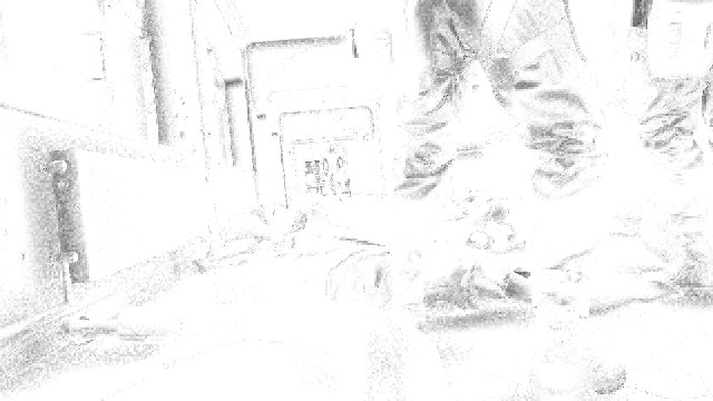
Velocity Map
To apply a motion blur effect as a post-process it’s necessary to know the velocity of each pixel on the screen.
If the scene is entirely static, it’s fairly easy to know each point velocity: it can be deduced from its depth and
the difference of the projection matrix between the previous frame and the current frame. But it gets more tricky when there are dynamic objects
like some characters who can run around, they can move independently from the camera.
This is where a velocity map comes into play: it stores the motion vectors (velocity) of each pixel of the current frame.
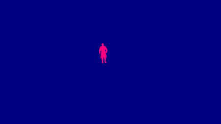
First the engine generates a velocity map only for the dynamic meshes like you see on the right.
Now you’ll notice in this particular scene only the Man on Fire is considered as a dynamic mesh.
Even if Snake and the soldiers are not static meshes technically, the engine treats them as such, which is acceptable in this case because they’re barely moving.
By doing so the engine can avoid some computation: animated characters need to be vertex-skinned twice (previous and current pose)
to calculate their velocity and it can be costly.
The red channel acts like a mask (set to 1 where the character is drawn), the actual velocity vector is written into the blue and alpha channels.
The Man on Fire isn’t moving so we have a dynamic velocity of (0, 0).
Next the engine computes the static geometry velocity from the current depth buffer and the last two projection matrices and
composites on the top the dynamic velocity map using the red channel as a blending factor.
This is the final velocity map (static and dynamic):
Don’t pay too much attention to the noise, there’s actually barely any movement in this scene: the camera is slowly zooming in on the Man on Fire, all the pixels have an almost null velocity, what you see are rounding precision errors when the components are written to 8-bit channels. I simply boosted the colors to make the image more readable, I also swapped the green and alpha channels, the actual buffer stores the velocity in the blue and alpha channels.
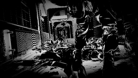
Screen Space Ambient Occlusion
The SSAO effect is supposed to add some darkening in areas with less ambient lighting, typically narrow holes or creases. Interestingly the Fox Engine performs two distinct passes of SSAO using different algorithms and combines the results with a final pass.
Line Integral SSAO
Line Integral SSAO is the ambient occlusion technique Avalanche Software
used in Disney’s Toy Story 3 game.
Despite its daunting name, the algorithm itself is relatively easy to grasp and very well explained
in this 2010 Siggraph talk:
for each pixel of the scene, a sphere centered on that pixel is considered, this spherical volume is then sub-divided into several “line-shaped” sub-volumes.
The occlusion factor of each sub-volume is calculated by performing a single tap in the depth map,
the total occlusion factor of the sphere is then simply a weighted-sum of each sub-volume’s factor.
Here the Fox Engine uses 2 pairs of symmetric samples, so a total of 5 taps per pixel if we include the original sample.
RGB: Linear Depth
|
Alpha: LISSAO
|
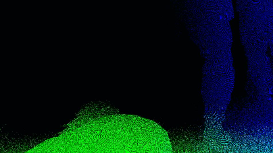
The calculation is performed at half-resolution and stored in a RGBA8 texture, with alpha containing the actual ambient occlusion result and
RGB containing the linear depth value (it’s a Float-to-RGB encoding, similar
to this technique).
The result in alpha is actually noisy due to a low number of samples, this SSAO map will be smoothed-out later with a depth-aware blur,
having the linear depth in the RGB channels means all the necessary data can be retrieved in a single tap.
Scalable Ambient Obscurance
The second SSAO pass uses a variation of the Scalable Ambient Obscurance technique.
It differs from the “official” SAO in the way that it does not rely on some depth mip levels and doesn’t reconstruct the normal, it reads directly the normal map
and works at half-resolution, performs 11 taps per pixel (though with a different strategy for sample locations).
It uses exactly the same medium contrast filtering and bilateral box-filter as the original SAO implementation.
Notice that the SAO parameters were tuned so that high-frequency variations (like on the soldier’s legs) really stand out compared to the LISSAO version.
In a similar way as the LISSAO, the SAO map is blurred with 2 depth-aware lateral passes.
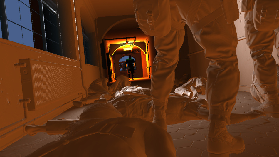
Then a compute shader combines the LISSAO and SAO images together to produce the final SSAO result:
Irradiance Spherical Maps
To deal with global illumination the Fox Engine relies on local irradiance spherical maps: different areas are defined in the level and for each of these areas one spherical map approximates the irradiance coming from different directions.
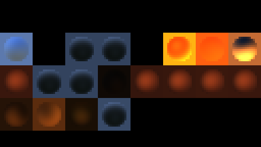
This step generates all the spherical maps which are used in this scene, one by one, and stores each into a 16x16 tile of an HDR texture atlas. This is this texture atlas you can see on the left: the disk in the middle of each tile is roughly what a metallic sphere would reflect if it was placed in the middle of the irradiance zone it represents.
So how were these spherical maps generated? They are computed
from spherical harmonics.
The mathematics behind it can be scary but spherical harmonics are just a way to encode the value of a 360° signal into
a set of coefficient, typically 9 coefficients provide a good-enough precision (2nd order SH).
And just from these 9 numbers you can roughly reconstruct the signal value in any direction.
If you’re familiar with the concept of how
a Fourier transform
can break a signal into component sine waves it’s a bit similar except here we’re decomposing the signal into functions on the surface of a sphere.
Where do these coefficients come from? They’re calculated offline, my guess is that the environment of each area marked by the level designers is captured into a cubemap. It is then converted to an irradiance cubemap and encoded into spherical harmonics coefficients that will be fetched by the engine at runtime.
So you might wonder why cubemaps are not used directly to represent the irradiance. It would work, you could use irradiance cubemaps but they have drawbacks, the main one being the memory waste of storing the 6 faces of a cubemap whereas spherical harmonics bring down the cost to just 9 RGB numbers per map. It saves a lot of memory space and bandwidth on the GPU which is important when you’re dealing with dozens of maps in the scene.
All these spherical maps are generated every frame from the offline-baked spherical harmonic coefficients and the player’s current camera position and orientation.
Diffuse Lighting (Global Illumination)
Time to use all these irradiance maps we generated! Each zone affected by an irradiance map is sent to the GPU for rasterization.
Typically each draw call (one per irradiance map) sends a bounding-box-shaped mesh representing the volume of influence
in the world, the idea is just to be able to touch all the pixels which are supposed to receive some
influence from this particular irradiance map.
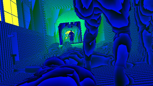
The diffuse map is computed in a half-resolution HDR texture, reading from the normal, depth and irradiance map.
|
Normal
Depth
Irradiance
|
|
Diffuse (GI): 15%
Diffuse (GI): 30%
Diffuse (GI): 80%

Diffuse (GI): 100%
|
The process is repeated for each irradiance map, with additive blending of the new fragments on the top of the old ones.
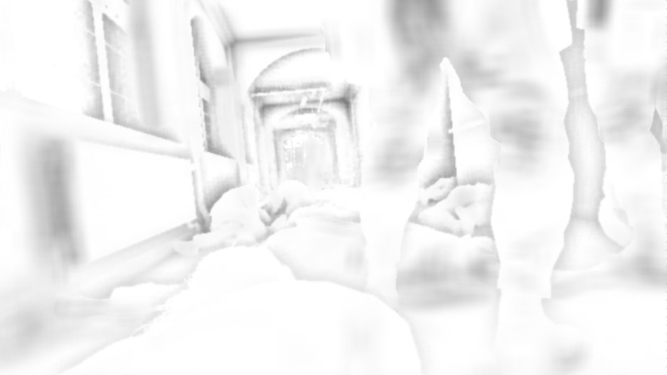
After all the lighting contributed by the global illumination has been accumulated into this diffuse buffer, it gets upscaled from half to full resolution. Note that the upscaling isn’t a naive bilinear-filtering though, it’s a bilateral upscale which reads the half-resolution buffer and also, more importantly, the original full-resolution depth map (to attribute weights to neighbor color pixels) so the final result still has crisp edges around the mesh borders. Visually it almost looks like we’ve been rendering at full-resolution the whole time!

2x Upscale (No Filtering)
|

2x Bilinear Upscale
|

2x Bilateral Upscale
|
Non-Shadow-Casting Lights
After all this static diffuse lighting from the global illumination, now is time to add some dynamic lighting contributed by point lights and spot lights. We are working at full resolution and render one by one a volume of influence for each light of the scene, for now only the lights which don’t cast any shadow are rendered:
Actually at the same time the diffuse lighting buffer was being updated, another render target also HDR full-resolution was being rendered too: the specular lighting buffer. Each light draw call you saw above was writing to the diffuse and specular buffer simultaneously.
Shadow Maps
You can guess what’s coming after the non-shadow-casting lights: the shadow-casting lights!
These lights are much more expensive so their number is usually quite limited in games, the reason they’re costly is that they
require a shadow map generation each.
It basically means rendering the scene again from the point of view of each light.
Here we have 2 spot-lights in the hallway ceiling casting light downward, a 4k x 4k shadow map is generated for each.
Shadow-Casting Lights
Now that the shadow maps have been generated, the lighting of the 2 ceiling spot-lights is computed. Both the diffuse and specular buffers are updated at the same time. Finally the sunlight is applied (from a spherical harmonics sphere map previously generated).

Diffuse 0%
|
Specular 0%
|
Diffuse 30%
|
Specular 30%
|
Diffuse 70%
|
Specular 70%
|

Diffuse 100%
|
Specular 100%
|
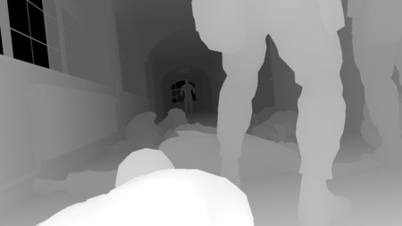
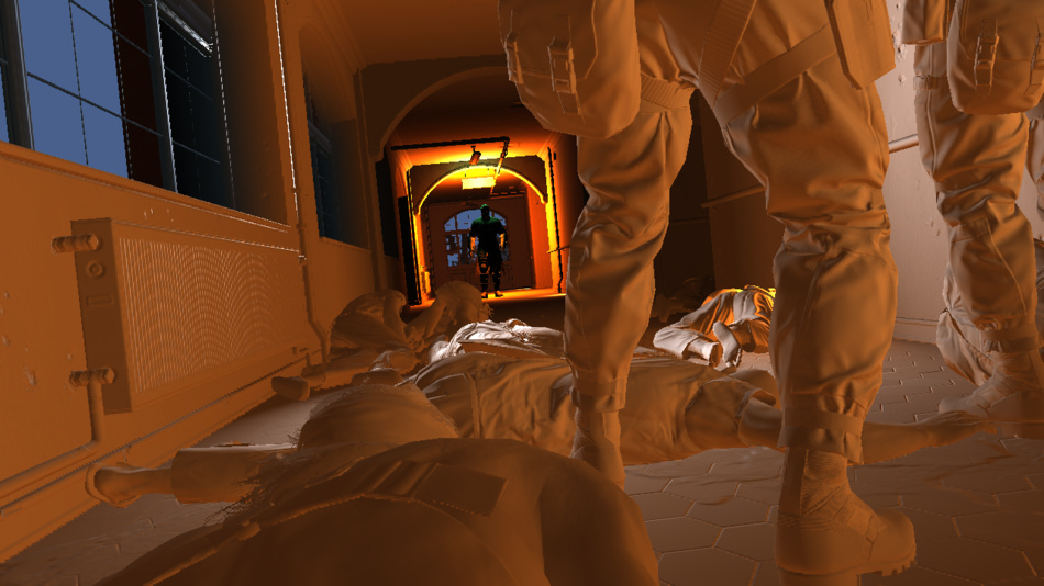
Lighting Combination and Tonemap
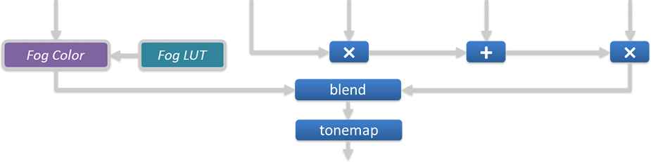
This step combines together all the buffers we’ve generated: the albedo color is multiplied by the diffuse lighting, to which the specular is added. The color is then multiplied by the SSAO value and the result is interpolated with the fog color (which is itself derived from a fog look-up texture and the current pixel’s depth). Finally the tonemapping is applied to convert from an HDR space to a LDR space. The alpha channel stores some additional information: each pixel’s original HDR luminance.
|
Depth
|
Albedo
|
Diffuse
|
Specular
|
SSAO
|
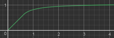
Which tonemapper is used in MGS V by the way? It’s completely linear between 0 and a certain threshold (0.6) and returns the original channel value,
then above the threshold it slowly grows to an horizontal asymptote.
Here is the function applied to each RGB channel, with $math$
\text{$A = 0.6$}
$math$
and
$math$
\text{$B = 0.45333$}
$math$
:
$math$ ToneMap(x) = \begin{cases} x & \text{if $x \le A$} \\[2ex] min\left( \text{1 , } A + B - \large{\frac{\text{$B$ ²}}{x - A + B}}\right) & \text{if $x \gt A$} \end{cases} $math$
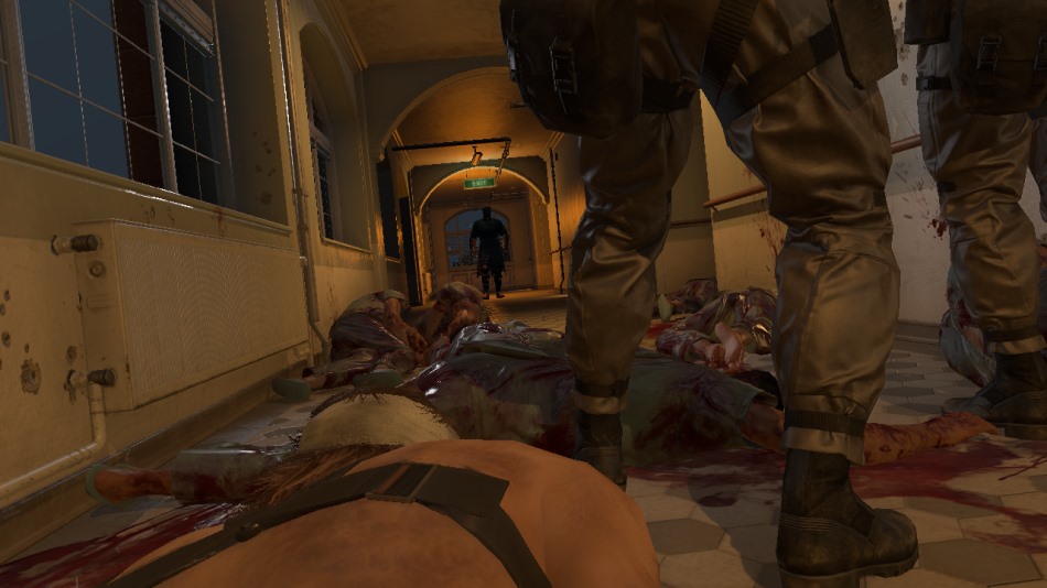
So the tone-mapping was applied as well as the gamma correction
to go from a linear space to sRGB space. In other games it often means we’ve reached the final steps of the frame rendering.
Are we done here too? Not at all, we’re just getting started! Interestingly the Fox Engine performs tone-mapping quite early
and continues its work in LDR space, including passes for transparent objects, reflections, depth of field…
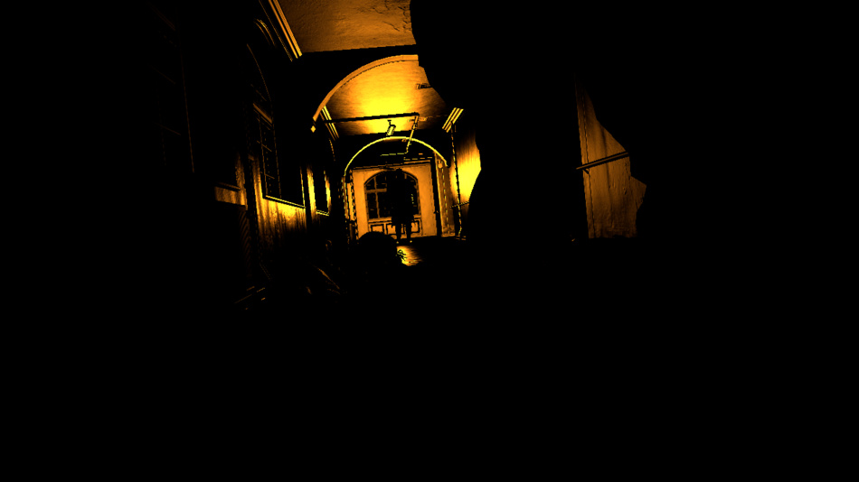
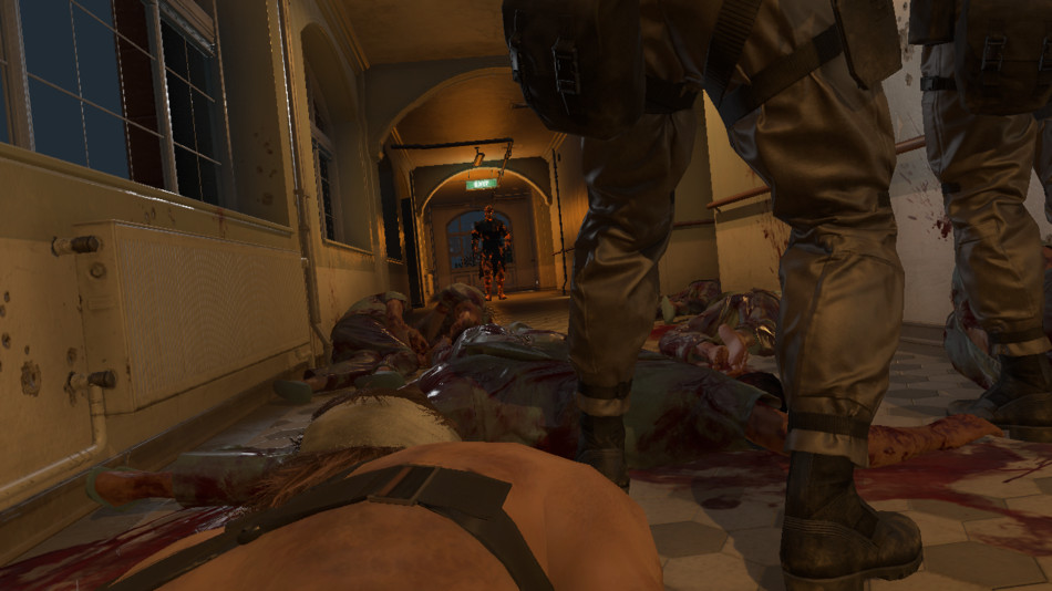
Emissive and Transparent Objects
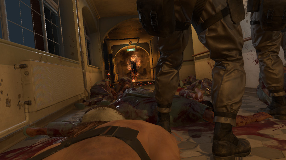
In this pass the engine draws all the objects with an emissive property like the green “Exit” sign or the incandescent flame spots on the Man on Fire. It also draws transparent objects like glass.
It’s not really visible in the screenshot above but in the case of glass, the reflection from the environment is also applied.
All the environment data is fetched from the 256x256 HDR cubemap you can see below (also called reflection probe).
The cubemap is not dynamic, it’s only baked once offline and used as-is at runtime so you won’t see any dynamic meshes inside.
Its role is to provide “good-enough” reflection of the surrounding static environment data. There are several probes like this throughout the level
at different locations. The total number of cubemaps for the entire game is huge, not only you need probes in lots of locations,
you also need different versions of the same probe depending on the hour of the day/night.
Plus you also need to take into account the weather so for a same location at the same hour the engine generates 4 cubemaps for sunny,
cloudy, rainy and stormy weather. The game needs to deal with an impressive amount of permutations.
A short clip was played at the GDC 2013 showing the engine generating such light probes.
Screen Space Reflections
This step constructs a reflection image of the scene using only information from the pixels we’ve rendered in the previous pass. It performs some ray-casting in screen space at half-resolution: a number of rays are shot for each pixel of the screen, the direction of these rays is calculated from the depth buffer (giving the pixel position) and its normal. Each ray is tested for collision by sampling the depth buffer at 4 equidistant points located along the ray. If a hit is found the color of the pixel where the hit happened is used as a reflection color, modulated by the original pixel roughness.
SSR Color
|
SSR Alpha
|
We obviously lack “global” information: any object outside the screen is unable to contribute to any reflection. To make artifacts less noticeable
the reflection map uses an alpha mask to smoothly fade-out the opacity as we get closer to the screen edges.
The SSR value lies in the fact that it can provide realtime dynamic reflections for quite a cheap price.
The noise in the SSR map is later reduced with a Gaussian blur and blended on the top of the scene.
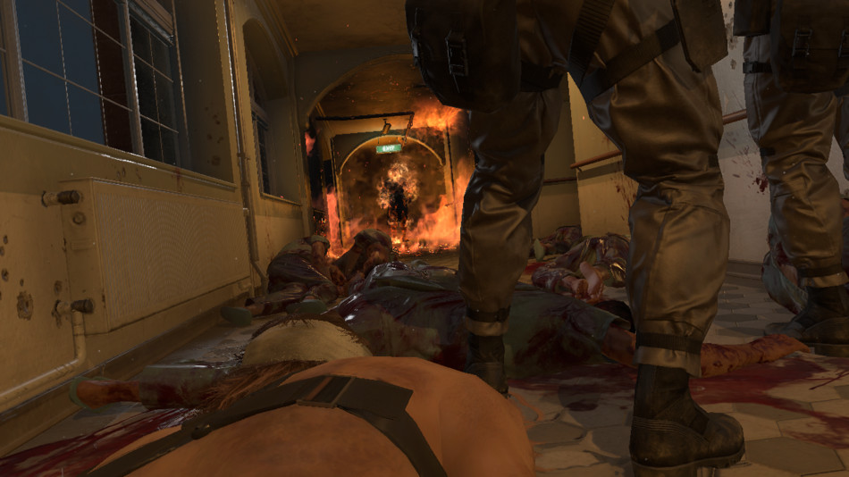
Heat Distortion, Decals and Particles
The burning area where the Man on Fire is standing has a temperature so high it creates light distortion. The effect is achieved with several draw calls,
each making a copy of the entire render target and applying a distortion by stretching the pixels along some direction locally.
It’s especially visible on the first arch connecting the left wall to the ceiling.
After that some decals are applied like the liquid on the floor and finally particles are drawn to render the fire and the smoke.


Bloom
This step creates a bloom texture from the original scene. It works at very low resolution: first the scene is downscaled by a factor of 4 then a bright-pass filter is applied to make only the brightest pixels stand out just like you can see on the image on the right.
How does the bright-pass filter discriminate between “dark” and “bright” pixels? We’re not in HDR space anymore, we’re post-tonemap in LDR space where it’s more tricky to know which color was originally bright. Well remember that the scene buffer alpha channel contains the original HDR luminance of each pixel pre-tonemap, this is this information the filter uses to decide how “bright” a pixel actually is.
In the Fox Engine the bloom is not just about bright pixels spreading their colors around: it also takes into account lens flares and chromatic aberration which are procedurally generated from the bright-pass buffer. Here in this dark scene there’s no strong light source making the lens flares stand out, they’re barely visible but you can get an idea of what they look like with the image on the right where I artificially boosted the colors.
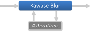
Lens flares get composited on the top of the bright-pass filter, then a large-radius blurred version of the buffer is generated, by running 4 consecutive iterations of Masaki Kawase’s blur algorithm. Kawase’s approach is able to achieve large-radius blur similar to Gaussian but at higher performance.
|
|
|

Bloom
|
Depth of Field
The Metal Gear games are known for their long, movie-like cinematics so it’s natural the engine tries as hard as possible to replicate the behavior of real world cameras with a depth-of-field effect: only a certain area appears sharp, the other out-of-focus areas appear blurred.
The scene is downscaled to half-resolution and converted back from sRGB space to linear space.
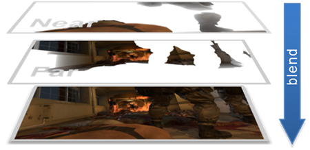
Then the engine generates 2 images corresponding to the “near field” (the area between the camera and the focus distance)
and the “far field” (the area beyond the focus distance).
The discrimination is purely depth-based (distance from the camera), any pixel closer than the soldiers will be copied to the near field buffer, and
other pixels further away will go to the far field buffer.
Each field is then processed separately to apply some blur. Each pixel’s Circle of Confusion is calculated based simply on its depth and
the camera configuration (aperture, focal distance…), the CoC value basically says how much “out-of-focus” a pixel is, the bigger the CoC the more the pixel
color spreads around.
Here are the 2 fields once the blur has been performed:
|
DoF - Near Field
|
DoF - Far Field
|
![]() A few words about this “blur” operation: it’s actually a relatively heavy operation where one sprite is spawned and rendered for every single pixel of the scene.
The sprite itself contains a disk like you can see on the right, you could replace it by any shape, an hexagon for example if you prefer hexagonal bokeh…
A few words about this “blur” operation: it’s actually a relatively heavy operation where one sprite is spawned and rendered for every single pixel of the scene.
The sprite itself contains a disk like you can see on the right, you could replace it by any shape, an hexagon for example if you prefer hexagonal bokeh…
The sprite will be centered on the pixel which spawned it, it has the same color as the pixel and its size scales with the pixel CoC.
The idea is that you want pixels to “spread their color around” using this disk shape, the more out-of-focus a pixel is the larger the sprite it spawns should be.
 All the sprites are drawn on the top of each others with additive blending.
This technique is a “sprite scattering” approach, it’s used in several games like Lost Planet, The Witcher series or UE4’s Bokeh-DoF post-process.
Once our blurred far and near fields are generated we just simply blend them on the top of the original scene:

This technique works and produces beautiful results, though it can quickly become a performance hog at high resolution with strongly out-of-focus scenes:
very large sprites overlapping each others can cause some crazy overdraw.
So how does the Fox Engine mitigate this issue?
Well I actually over-simplified my explanation above when I wrote one field is
represented by an half-resolution accumulation buffer,
it’s not just this one buffer there are also other smaller ones at ¼th, 1/8th, 1/16th of the resolution. Depending on the pixel CoC, the sprite it spawns
will end up in only one of these buffers: typically big sprites go to low-resolution buffers to reduce the total number of pixels touched.
In order to do this the engine treats each buffer level one after another, spawning 100% of the sprites and letting the vertex shader kill
the sprites not belonging to the current level. The vertex shader knows from the original pixel’s CoC the final size the sprite will have,
if this size is not appropriate for the current level the shader just kicks the vertex outside the frustum by setting a negative depth value.
The sprite geometry never makes it to the rasterization stage by the pixel shader.
All these buffers then get combined to produce one half-resolution field.
Lens Dirt and More Lens Flares

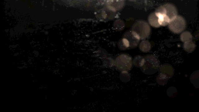
Snake is in a difficult situation in an hostile environment, with explosions all around, some projections are going to hit the camera lens and make it dirty. To reflect this a bit of lens dirt is added artificially on the top of our image, the dirt is generated from some sprites.
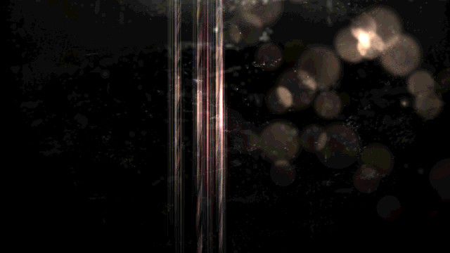
Then we need more lens flares! Yes we already added a few of these before but there’s nothing like too many lens flares, right? This time we add anamorphic lenses artifacts: the long vertical light streaks in the middle of the screen, caused by the bright flames. These are also generated purely from sprites.
All these steps are performed with a dozen draw calls rendering to a half-resolution buffer which is then composited on the top of the scene with additive alpha-blending.

Motion Blur
You remember we’ve generated a velocity buffer at the beginning of the frame? It’s finally time to use it to apply some motion blur to the scene. The technique used by the Fox Engine is inspired by the MHBO 2012 paper.
It generates a low-resolution map with square tiles containing the maximum velocity of its pixels. The image of the scene is locally stretched along the direction of the velocity vectors to create an impression of movement. Here the motion blur effect is hard to visualize because there’s barely any movement in this scene.
Color Grading
Color grading is about adjusting the final color of the scene.
The artists can decide to balance the colors, apply some filters…
This is done by an operation which takes the original RGB value of a pixel and matches it to a new RGB value, all in LDR space.
In some cases you can come up with some mathematics function to perform such conversion (it’s what a tonemapping operator does
when it converts from HDR to LDR), but usually artists want more advanced control over the color conversion and no mathematics function
will get the job done.
In this case we have to bite the bullet and consider the brute force approach: a big look-up table
(LUT) mapping every single possible RGB value
to another RGB value.
Sounds crazy? Let’s see: there are 256 x 256 x 256 possible RGB values, that’s more than 16 million mappings to maintain!
This will be hard to feed efficiently to a pixel shader… unless we resort to some trick.
And the trick is to consider the RGB space as a 3-dimensional cube, defined by 3 axes: red, green and blue.
|
RGB Cube
|
Then we take this cube on the left, cut it into 16 slices and we store each slice into a 16 x 16 texture. We end up with the 16 slices you can see on the right. |
LUT
|
So we now have “discretized” our cube down to 16 x 16 x 16 voxels, so 4096 mappings, which is just a tiny fraction of the original 16 million entries.
How do we reconstruct all the other missing entries? By linear interpolation:
given some RGB color just look for its 8 nearest neighbors in the cube
for which we know the exact mapping.
In practice that means finding the 2 layers closest the blue value, then inside each layer finding the 4 closest pixels to the red and green values.
Then it’s a just a linear interpolation: a weighted average of the 8 colors using the distance to influence the weights.
Such interpolation from a small number of values works because color grading is usually about low-frequency variations.
You can store your 16 layers into a 3D texture on the GPU and then the shader code is dead simple: just ask for a lookup at some 3D coordinates and the hardware transparently performs the trilinear filtering of the 8 closest points and returns the correct value. Fast and easy.
So we have a way to encode color mapping through this 16-slices-LUT, but how can the artist actually create such LUT?
It’s quite straight-forward, just lay-out all the slices next to each other to produce an image like this:

256x16 LUT texture
Then take a screenshot in the game of some scene that requires color-grading. Embed the LUT image above in some corner of the screenshot, give the image to the artists and let them do the magic. They’ll use their favorite image editor, make adjustments they like, when they’re done and send you back the corrected picture, the LUT you embedded in the corner will reflect the new RGB color mapping. You can simply extract the modified 256x16 LUT and feed it directly to the game engine.
LUT
LUT

In this step the bloom buffer was added on the top of the scene before applying the LUT color-grading.
Anti-Aliasing


The mesh edges follow a bit too much the pixel grid of the frame buffer, we can see hard jagged borders which look unnatural.
This is a limitation of a deferred renderer where each pixel stores only a single information; in a forward renderer it would be less of an issue, you could rely on MSAA to have multiple color samples per pixel which produces softer edge transitions.
Here the Fox Engine fixes some edge-aliasing by performing a post-processing pass of FXAA:
a pixel shader tries to recognize and fix aliased edges based on the color values of the neighbor pixels.
Notice how all the stair-case visible at the border of the handrail is smoothed-out in the final result.
Final Touch
Are we finally done after anti-aliasing? Not quite but almost! In this last step the artists have the possibility to apply some masks in certain areas of the image to darken or lighten the pixels. These are just a series of sprites drawn on the top of the scene. It’s interesting to see how far the Fox Engine goes to keep artists in control up until the very last step of the rendering.
And we are done! The frame can now be sent over to the monitor for display and the GPU will begin this same process again from scratch to generate a whole new frame.
A few metrics about this particular scene: 2331 draw calls, 623 textures and 73 render targets were used.
Bonus Notes
Watch the Buffers in Motion
Here is a short clip showing the different buffers I presented before (G-Buffer, SSAO…) live while playing the game.
If you’re curious about how this video was made: it turns out this study required quite a bit of effort compared to my previous ones,
none of the graphics debuggers out there were usable because MGS V will shutdown when it detects
DLL injectors
tampering with certain D3D functions.
I had to get my hands dirty and forked an old version of ReShade I extended with my own custom hooks so I could dump
intermediate buffers, textures,
shader binaries (the DXBC containing all the debug data)…
Once I had my own runtime hooks it was fairly easy to produce the video above: I could just copy any intermediate buffer I wished to the
final framebuffer right before it goes to the monitor.
Update: Due to popular demand I made my ReShade customization available here. Grab it and have fun!
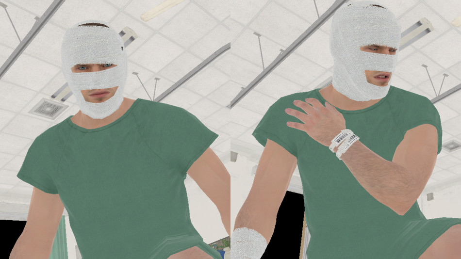
Ishmael’s True Face
Ishmael is the mysterious patient in the bed next to Snake who helps him escape the hospital.
His head is covered with bandage concealing his true identity.
Ever wondered what his face really looks like?
Well let’s have a look! Here is the diffuse albedo buffer right after and before the bandage is rendered.
No spoiler here. The slide-show is set to manual-play just in case, watch it only if you wish. Won’t really spoil anything…
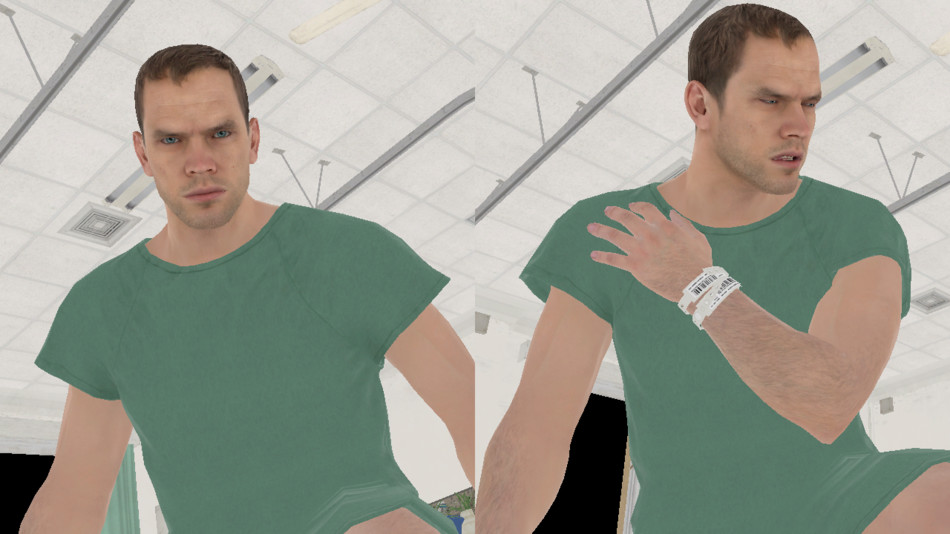
But let’s push this a bit further!
Instead of just dumping the albedo map in the middle of the G-Buffer generation like I did above,
it would be nice to see Ishmael’s face while playing the game live, by preventing the engine from rendering the bandage.
This is fairly easy to do: with the custom hooks I can choose not to forward certain calls to the GPU, after poking around a little
I could identify the 2 draw calls responsible for the bandage rendering and blacklist them.
If you want to reproduce my experiment at home these are the calls in question:
1 2 | |
And below is a video of the game with Ishmael’s true face. I’m using a hot-key to toggle the bandage rendering on/off. The transition is progressive by slowing decreasing the number of triangles used to draw the bandage until complete fade-out.
Note that this trick of blocking draw calls won’t work in all cases, sometimes the original mesh simply doesn’t have the data for the hidden surfaces.
Which makes sense for optimizing performance: less unnecessary geometry pushed to the GPU!
For example the model of Tretij Rebenok doesn’t have any triangles underneath
the gas mask for the bottom of his face, you’ll never see his nose and mouth simply because they don’t exist.
More Links
This concludes the analysis of MGS V, I hope you could get a better understanding of how the Fox Engine renders a frame.
If you’re eager to know more below is a selection of links with extra material:
- Photorealism Through the Eyes of a FOX: The Core of Metal Gear Solid Ground Zeroes (GDC 2013) by Kojima Productions
- Tech Analysis: Metal Gear Solid 5’s FOX Engine by Digital Foundry
- MGS V PBR Texture Analysis documenting map formats.
- MGS V NVIDIA Performance Guide with details about graphics settings.
- ReShade, special thanks to Patrick Mours for open-sourcing it earlier this year.
More discussion on this topic: Hacker News, Reddit.