
At my day job I get to optimize several games for the Nintendo Switch
or the NVIDIA Shield,
some of them using Unreal Engine 4.
While UE4 is very powerful and offers a large selection of knobs to balance visual quality
and performance some of the post-effects can end up
being significantly heavy on a Tegra X1 GPU even at the lowest quality settings.
Below is a small collection of customizations/hacks I wrote in order to optimize the runtime cost of certain effects while remaining as close as possible to the original visuals of a vanilla UE4. The idea is to provide a drop-in replacement you can easily integrate into your own game to achieve better performance on a X1. Here I will be mainly writing about:
Bokeh Depth-of-Field
Depth-of-field techniques have seen a lot of changes recently in the latest UE4 versions, some getting deprecated in favor of the new DiaphragmDOF implementation. Historically UE4 supported 3 different approaches:


Here I will be writing about a drop-in replacement for BokehDOF called GatherDOF.
BokehDOF produces very pleasant visual results but the main issue is its bandwidth cost.
To give some idea of how BokehDOF operates, it basically spawns one bokeh sprite per original pixel of the scene, each sprite size being proportional to
the circle-of-confusion value of the pixel it originates from.
(See also the MGS V graphics study for more in-depth insights, it’s using roughly the same method.)

BokehDOF Sprite
For a 1080p scene that means drawing around 2 million quads, blended on the top of each other. As pixels get furthermore out-of-focus the sprite size increases and performance takes a nose-dive with quad overdraw saturating the bandwidth.
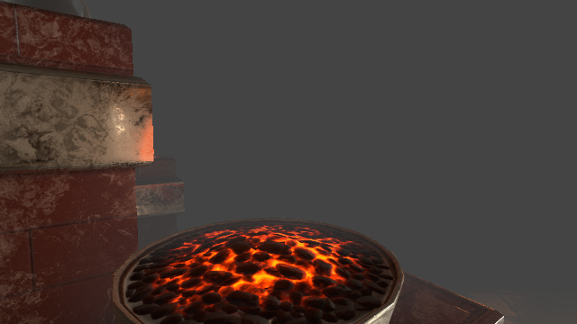
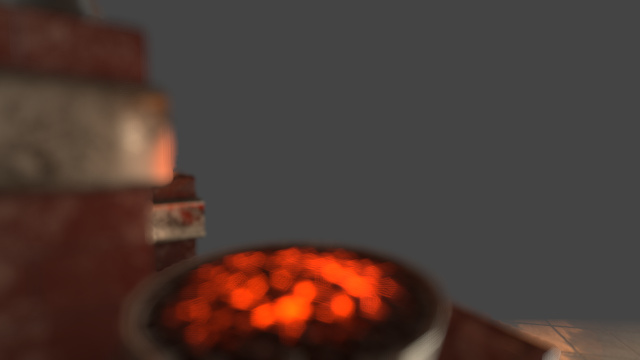
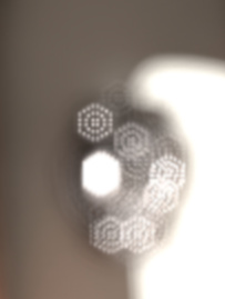
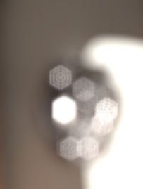
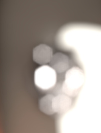
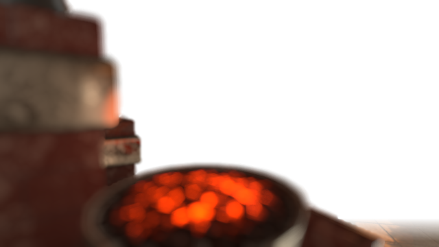
GatherDOF was implemented with the idea of producing a visual result close to BokehDOF but with a different approach: “gather” neighbor texel values instead of “scattering” bokeh sprites. The two algorithms are completely different — their cost as well — however the end result is quite similar visually:
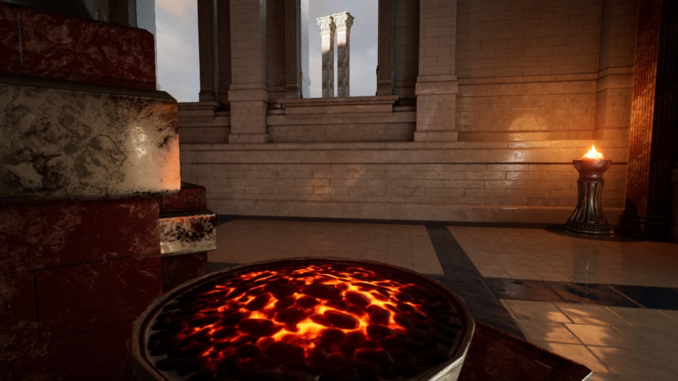
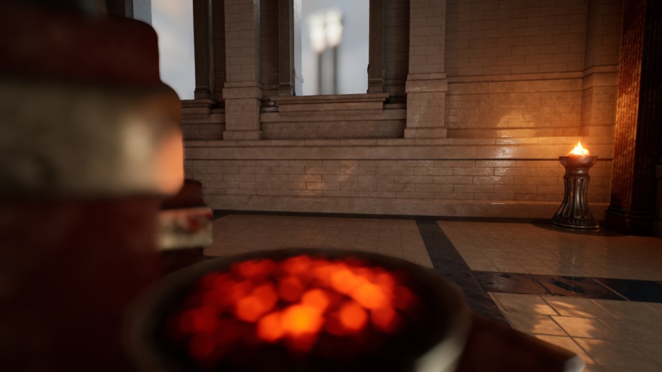
15ms
( TX1@768MHz )
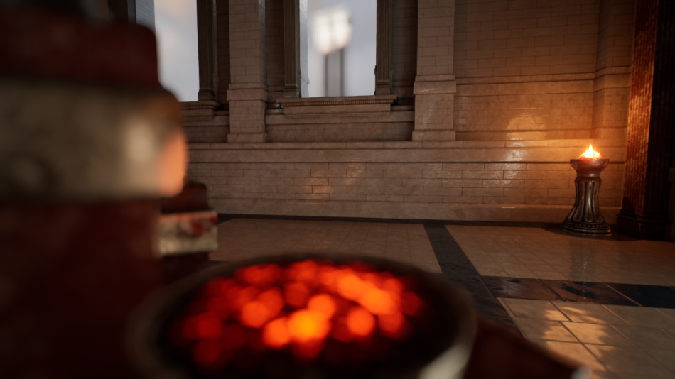
2ms
( TX1@768MHz )
Integration
Simply cherry-pick the commit below corresponding to your UE4 version below and recompile the engine.
| UE4 Version | 4.18 | 4.19 | 4.20 | 4.21 | 4.22 |
|---|---|---|---|---|---|
| GitHub Branch | Branch | Branch | Branch | Branch | Branch |
| Patch | Patch | Patch | Patch | Patch | Patch |
Choose either GitHub (requires account setup to avoid 404 error) or alternatively apply the patch manually.
Settings
CVar |
Description |
|---|---|
| Appearance | |
|
|
1 to enable GatherDOF, 0 to fallback to the original BokehDOF. |
|
|
Number of edges of the bokeh shape. 0: circle, 5: pentagon, 6: hexagon… |
|
|
Rotation to apply to the polygonal bokeh shape, in degrees. |
|
|
Scale factor to apply to the CoC radius value. |
| Scalability, Performance | |
|
|
High (1) or low (0) quality. Can increase tap count and reduce noise. |
|
|
Set to 0 to force-disable the treatment of the near-field. |
|
|
Set to 0 to force-disable the treatment of the far-field. |
|
|
Set to 0 to disable floodfill (noise reduction) for the near-field. |
|
|
Set to 0 to disable floodfill (noise reduction) for the far-field. |
|
|
Even if Temporal-AA is globally on, do not use it for smoothing DoF. (faster) |
How it works
To give a few details about GatherDOF implementation, the technique is based on the one used
in DOOM 2016, also present previously
in CryEngine 3.
The first steps are the same as BokehDOF: downscaling the scene to half-resolution,
with optionally Temporal-AA applied if it is enabled.
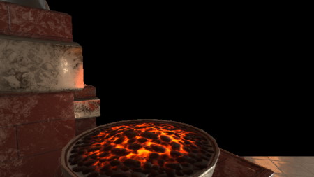
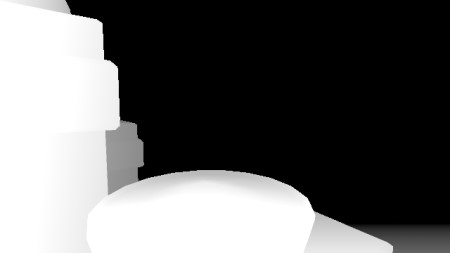
Then 2 buffers are extracted: the near and far field images, with their respective CoC stored in the alpha channel.
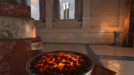
Scene Color
|
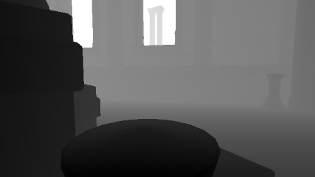
Scene Depth
|
![]()
|
Near-Field
|
Far-Field
|
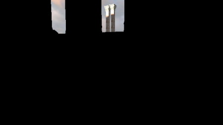
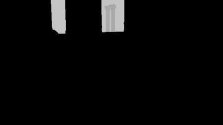
All the CoC calculation uses strictly the same logic as BokehDOF to guarantee an identical visual result.
Then a DOF blur is applied to each layer separately. This is done by performing a certain number of taps into the neighbor texels, the points covering a geometric area having the desired bokeh shape appearance. This can be a disk, an hexagon or any regular polygonal shape…
For example for a disk-shape bokeh, we want to sample some neighbor texels in a circular fashion but how do we do this?
One possible approach is to use
Shirley’s concentric mapping.
So if we have a square-grid of points — trivial to build — we can turn it into a disk point-cloud like this:
An example of HLSL implementation which re-maps a square-grid of points to a disk shape is as follows:
#define PI_OVER_2 1.5707963f
#define PI_OVER_4 0.785398f
#define EPSILON 0.000001f

// Maps a unit square in [-1, 1] to a unit disk in [-1, 1]. Shirley 97 "A Low Distortion Map Between Disk and Square"
// Inputs: cartesian coordinates
// Return: new circle-mapped polar coordinates (radius, angle)
float2 UnitSquareToUnitDiskPolar(float a, float b) {
    float radius, angle;
    if (abs(a) > abs(b)) { // First region (left and right quadrants of the disk)
        radius = a;
        angle = b / (a + EPSILON) * PI_OVER_4;
    } else { // Second region (top and botom quadrants of the disk)
        radius = b;
        angle = PI_OVER_2 - (a / (b + EPSILON) * PI_OVER_4);
    }
    if (radius < 0) { // Always keep radius positive
        radius *= -1.0f;
        angle += PI;
    }
    return float2(radius, angle);
}

// Maps a unit square in [-1, 1] to a unit disk in [-1, 1]
// Inputs: cartesian coordinates
// Return: new circle-mapped cartesian coordinates
float2 SquareToDiskMapping(float a, float b) {
    float2 PolarCoord = UnitSquareToUnitDiskPolar(a, b);
    return float2(PolarCoord.x * cos(PolarCoord.y), PolarCoord.x * sin(PolarCoord.y));
}
And this square-to-disk mapping is all we need to create a circular bokeh.
Great! But what if we want more fancy shapes like hexagonal bokeh?
Well we can actually apply a transformation to the radius while in polar space: the idea being that given an angle
, the radius
(which is alwasy 1 in the case of the unit cicle) can be scaled to follow a polygonal shape.
The formula for remapping the radius to a polygon with
edges is:
We can now apply this formula to our whole point-cloud and it will turn into a polygon where all the points are spread roughly uniformely over the entire surface:
And this can be implemented in a shader as:
// Remap a unit square in [0, 1] to a polygon in [-1, 1] with <edgeCount> edges rotated by <shapeRotation> radians
// Inputs: cartesian coordinates
// Return: new polygon-mapped cartesian coordinates
float2 SquareToPolygonMapping(float2 uv, float edgeCount, float shapeRotation) {
    float2 PolarCoord = UnitSquareToUnitDiskPolar(uv); // (radius, angle)

    // Re-scale radius to match a polygon shape
    PolarCoord.x *=                                      cos(PI / edgeCount)
                    / //----------------------------------------------------------------------------------------------
                    cos(PolarCoord.y - (2.0f * PI / edgeCount) * floor((edgeCount*PolarCoord.y + PI) / 2.0f / PI ) );

    // Apply a rotation to the polygon shape
    PolarCoord.y +=  shapeRotation;

    return float2(PolarCoord.x * cos(PolarCoord.y), PolarCoord.x * sin(PolarCoord.y));
}
That’s it! We now have all we need to apply a first pass of our bokeh blur filter.
For each input pixel we sample a set of neighbor pixels in a polygonal fashion, and compute a weighted-average of all the colors we found.
This is what the near field looks like after going through this pass:
It’s not shown here but in the case of the near field, the CoC map is actually downscaled to 1/8th of its original dimension (keeping the maximum value of the CoC in each tile) and blurred, then the bokeh sampling radius is based on the tile CoC value. This is done to avoid sharp transitions around the field borders. None of this is necessary for the far field which uses the original pixel CoC directly.
So we do have some nice bokeh shape taking form, but it’s not perfect yet some noise is clearly visible.
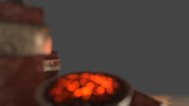
Let’s see it more closely on another example with isolated bright spots and a large radius:

How do we fix this?
We could brute-force and increase the number of taps (the r.GatherDOF.Quality CVar actually lets you bump the count)
but it’s more interesting to work-around the problem by adding a “flood-filling” pass.
The idea is based on the McIntosh filtering: sample neighbor pixels and only keep the maximum light intensity which was found.
This works surprisingly well to smooth-out any dark discontinuity within the bokeh shape.
(“max” filter)
And this is our near field before and after the flood-fill:
Note that if your bokeh radius is short enough the noise is barely visible even without flood-filling so
to squeeze a bit more performance you can always forcibly disable the flood-filling steps through the r.GatherDOF.Floodfill.Near and r.GatherDOF.Floodfill.Far CVars.
Finally we can combine our near and far fields on the top of the original scene.
This step also fetches the original depth-map in order to keep a sharp border for in-focus shapes over the
far field: unlike the fields (half-resolution) the full-resolution depth-map is able to tell exactly which pixel should stay in-focus.
Optionally the translucency buffer is also be fetched and applied
if UE4’s separate translucency setting is enabled.
![]()
And that wraps it up for a breakdown of the effect, it should produce a visual result quite close to the one of BokehDOF.
Pros and Cons
GatherDOF and BokehDOF are visually similar but let’s see in more details how they compare to each other.
Performance
At low-radius BokehDOF is faster because it touches very few pixels and doesn’t suffer from
the overhead of all the extra passes GatherDOF requires.
However at large radius BokehDOF performance quickly collapses and I have seen scenes
where GatherDOF outperforms BokehDOF by a factor of 10.
If your game uses a strong bokeh or some tilt-shift effect it might worth giving a shot to GatherDOF.
Noise
BokehDOF will produce the optimal result especially as the bokeh radius increases GatherDOF can become noisy.
Visual Customization
BokehDOF uses a custom sprite, which is the most powerful option from an artist perspective: perfect control of the shape
and chromatic aberration… GatherDOF can only use a polygonal shape without color aberration.


BokehDOF tends to produce fat hard-edge shapes which are especially visible with near-field objects on the top of background objects.
GatherDOF tries to fade-out the near field border to produce a smooth transition between the near field and the pixels behind it to give a more natural look to the image.
Another interesting artifact I noticed with BokehDOF is it sometimes fails to blur a thin border around the screen of the original image.
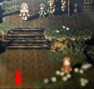
Border
Glitch
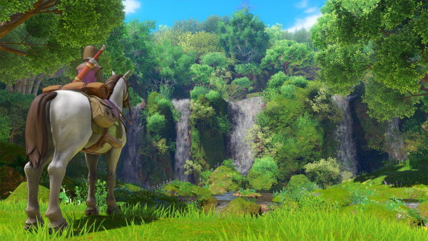
It’s visible in several UE4 games, for example Octopath Traveler uses a tilt-shift effect with a large radius DOF and suffers from this issue like you can clearly see in the trailer or in the screenshot on the right.
The bottom region is not blurred, it’s even more obvious when it’s in motion and this is something
hard to ignore once you notice it.
The moment I saw the trailer I knew almost certainly it was a UE4 game using BokehDOF.
So while GatherDOF can get noisy at high radius it doesn’t suffer from the glitches produced by BokehDOF when it comes to handling “borders”.
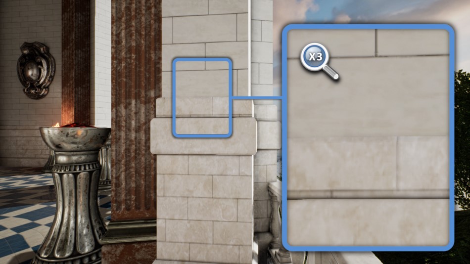
Screen-Space Ambient Occlusion
The SSAO in
UE4 is well optimized and usually runs fast but you can encounter serious slow-downs
when using a large SSAO radius.
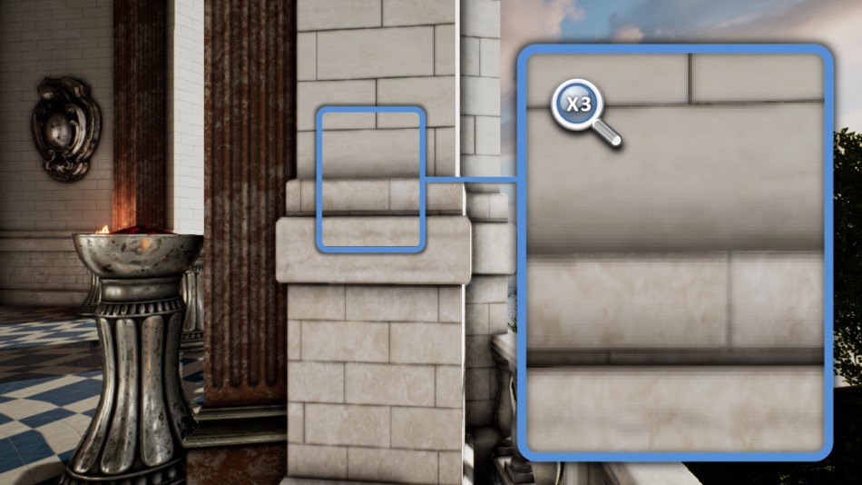
Even for a modest 720p depth-buffer it’s not uncommon to see the SSAO pass shooting up to 4 or 6ms on a X1@768MHz (at the SSAO lowest quality setting):
as the radius increases, depth-buffer taps get further apart from each other causing more texture-cache trashing.
Besides the performance aspect, the SSAO can look visually bad with a lot of noise visible when Temporal-AA is disabled.
The half-resolution patch I wrote improves on both of these issues: it brings a ~2x speed-up by working at half-resolution and smoothes-out the noise even when Temporal-AA is off (using a depth-aware blur).

4ms
( TX1@768MHz )
2ms
( TX1@768MHz )
Integration
Simply cherry-pick the commit below corresponding to your UE4 version below and recompile the engine.
| UE4 Version | 4.18 | 4.19 | 4.20 | 4.21 | 4.22 |
|---|---|---|---|---|---|
| GitHub Branch | Branch | Branch | Branch | Branch | Branch |
| Patch | Patch | Patch | Patch | Patch | Patch |
Choose either GitHub (requires account setup to avoid 404 error) or alternatively apply the patch manually.
Settings
CVar |
Description |
|---|---|
| Appearance | |
|
|
Set to 1 to enable half-resolution SSAO. |
Note that you are supposed to use this in combination with r.AmbientOcclusionLevels 1.
It’s also highly recommended to bump the Quality slider of the SSAO in the editor to 100% when you use half-resolution SSAO
because you need (and can afford!) more texture taps than in full-resolution.
This method is not compatible with the compute version (you must keep r.AmbientOcclusion.Compute to 0), the pixel shader version is
to be preferred anyway on X1.
How it works
The SSAO algorithm itself is unchanged because we need to keep the same look, it simply runs at half-resolution.
We obtain a first noisy result which is then smoothed by using a depth-aware blur: it’s a
separable Gaussian kernel applied first horizontally,
then vertically. The important trick is to adjust each tap weight depending on their depth distance from the reference pixel:
neighbors for which the difference is too high should be discarded, so we avoid some
shadow “bleeding” onto unrelated meshes.

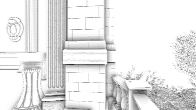

When Temporal-AA is off this method generates results more pleasant than the UE4 vanilla implementation:
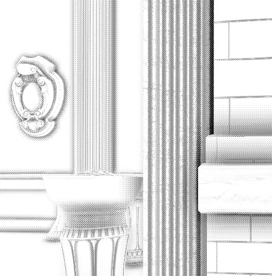
SSAO - Original
|
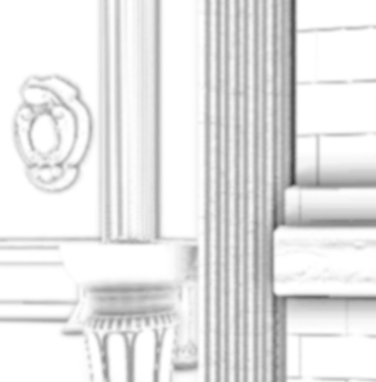
SSAO - Half-Resolution
|
Pros and Cons
Let’s see how the half-resolution mode compares with the original version.
Performance
In terms of speed the half-resolution beats the full-resolution method by factor of ~2 for large radius values. And this is by comparing the full-resolution at the lowest quality versus half-resolution with the quality set to 100%.
Visual Aspect
If you are not using Temporal-AA, the vanilla SSAO can look too noisy, switching to the half-resolution mode with depth-aware blur should be a no-brainer.
If you can afford Temporal-AA in your game, the vanilla SSAO is potentially better and suffers less from aliasing (because it has twice the pixel density and more information to work with).
Make sure you bump the SSAO Quality slider in the editor to 100%, lower-resolution allows performing more taps.
Note that if you encounter any kind of noise or artifact with the half-resolution mode, or something that looks like
some Moiré-pattern, try forcing:
USE_SAMPLESET 2 and SAMPLE_STEPS 2 inside the PostProcessAmbientOcclusion.usf shader. These parameters are usually controlled by the SSAO Quality slider in the
editor (5 different levels), unfortunately there’s no quality level corresponding to these specific sample values. This configuration in particular usually
strikes a very good balance between artifact reduction and performance (texture taps count).
// ...
#else // SHADER_QUALITY == 4
    // very high
    #define USE_SAMPLESET 3
    #define SAMPLE_STEPS 3
    #define QUAD_MESSAGE_PASSING_BLUR 0
#endif

// Add the following lines
#undef USE_SAMPLESET
#define USE_SAMPLESET 2
#undef SAMPLE_STEPS
#define SAMPLE_STEPS 2
// ...
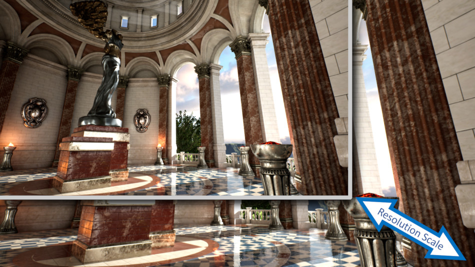
Dynamic Resolution
The 3rd engine customization I introduce here is not a post-effect,
the concept behind dynamic resolution is to adapt the resolution the scene is rendered at depending on the GPU load.
In heavy areas the GPU might struggle to render a frame in a certain time budget, in this case the renderer
can lower the resolution to avoid frame drops. When the GPU load gets lighter, the renderer can automatically
increase the resolution to fill the extra budget available and produce higher quality visuals.
Dynamic resolution coupled with temporal upscaling started to appear in UE4.19. However UE4.18 and prior have no concept of dynamic resolution. Fortunately it’s fairly easy to hack up a quick solution that will adjust the scene resolution depending on the GPU time of the previous frames.
Integration
Simply cherry-pick the commit below corresponding to your UE4 version below and recompile the engine.
Choose either GitHub (requires account setup to avoid 404 error) or alternatively apply the patch manually.
Settings
CVar |
Description |
|---|---|
|
|
1 to enable dynamic resolution. |
|
|
Maximum screen percentage we allow the renderer to use when the scene is light. |
|
|
Minimum screen percentage we allow the renderer to fall down to when the scene gets very heavy. |
|
|
Defined in ms. When rendering time exceeds this value, we switch to a lower resolution to reduce burden on the GPU. It’s better to be conservative: for a 60FPS budget, 14 or 15 values are better than 16 to avoid frame drops. |
|
|
Defined in ms. When rendering time is lower than this value, we’re fast enough to switch to higher resolution, increasing quality and GPU load.
The value should be much lower than |
Also set r.SceneRenderTargetResizeMethod 2 to avoid hitches during resolution changes:
we don’t want render targets to be re-allocated upon each resolution change, we want them to
stay at the maximum size with only the viewport varying.
How it works
Internally it works the same way as if the renderer was modifying r.ScreenPercentage on-the-fly
(although it doesn’t actually touch this CVar, it only applies a factor to it when choosing the resolution).
The result is all the GBuffer and post-effect generations are done at a resolution which can change every frame depending on the GPU load:
resolution decreases under heavy GPU load to avoid dropping frames, and resolution increases when GPU load is light to improve visual quality.
The GPU load is calculated using 2 GPU timestamps which are triggered at the beginning and end of the frame. Depending on your platform make sure that
the RHI correctly reports the engine global variable GGPUFrameTime.
The provided patch is extremely basic and bounces between 2 preset resolution factors. But you are free to customize the logic to your own needs, with other intermediate resolution levels…
Pros and Cons
This dynamic resolution system is “reactive” in the sense it can only know the GPU time of a frame after it has happened.
The last frame time cannot be retrieved immediately: we don’t want to stall the pipeline to read the timestamps.
So while the system does its best to anticipate frame drops, it cannot guarantee it will completely prevent them.
The rescaling logic is fully customizable and should be as conservative as possible to avoid frame hitches:
that means downscaling aggressively when the GPU gets dangerously close to its budget, and upscaling prudently when the load is lighter.
This system does not play nice with temporal effects like Temporal-AA, motion blur or SSR, you might see brief glitches with these passes when the resolution changes. If your game uses these effects I would simply recommend to switch to UE4.19 or later and take advantage of the powerful temporal upscaling which was added to the engine and also has a dynamic resolution logic.
Conclusion
I made this collection of patches public in the hope they can be useful to others optimizing their UE4 games, even if stuck on
an old version — not all game projects can afford the luxury of upgrading to a newer engine with all the bells and whistles.
Some of the methods here were robust enough to ship in several high-profile games so don’t be afraid to try them out and see if they work for you.
UE4 is an ever-evolving codebase and while I’m trying my best to keep the patches in sync with newer engine versions, I can’t make any promises about future versions.
Feel free to reach out with feedback!
Code-License: I originally made these patches freely available, no strings attached, I don’t mind not receiving attribution.
But I was told that not having a proper (corporate-friendly) license can hinder code integration in certain companies.
So I’ll add as a precision:
all the patches and code above are dual-licensed both under
CC0/Public-Domain
and
MIT.
Update - Game Example: Dragon Quest XI S
This is a small addendum since I wrote above that these customizations were used in games, and now that the information is public I can mention that:
Dragon Quest XI S: Echoes of an Elusive Age – Definitive Edition which released on the Nintendo Switch in September 2019 makes use of both the dynamic-resolution and half-resolution SSAO features described previously.
I had the privilege to work with Square-Enix
on this title to integrate these modifications into their version of UE4.
Plus some other work still under NDA I am not at liberty to discuss yet…
Keep in mind this is originally a PS4 game which had to be crammed down to run a Nintendo Switch, with all the challenge it implies in terms of CPU, GPU, storage size.
Many of the optimizations performed were presented at a session of Unreal-Fest Japan 2019 in Yokohama.
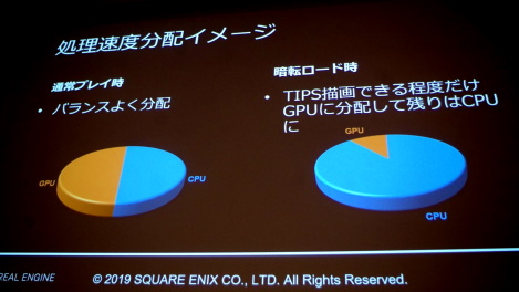
Nintendo added the CPU-overclock mode to the Switch to shorten load times,
at the request of Square Enix’s Kamiyama-san.
|
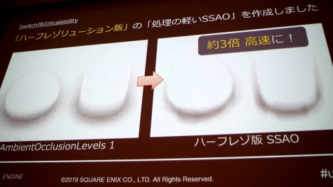
3x speed-up and higher quality in the SSAO pass from switching to
the half-resolution version.
|
The full list of slides (in Japanese) is available on the Famitsu website.
Update 2: Pikmin 4
 Pikmin 4 shipped a with a modified version of GatherDOF presented above.
I had the privilege to work
with Nintendo EPD
and Eighting
to integrate the DoF into their fork of UE4.

|

|
Simulating a miniature-effect through a very shallow depth of field, to give an impression of close-up photography was a crucial aspect of Pikmin 4 visuals.